Are you good at soldering? If so, and you’d be prepared to do a bit of soldering at home for us, Swindon Panel wants to hear from you!
Our new simulator, which has been under research and development for the last two years, requires a lot of PCBs to interface it with the panel (approx 350). These have been designed in-house and produced, and all the components have been delivered. All we need now is for the components to be soldered on.
If you are good at soldering and would be happy to have some boards and components posted to you for you to solder up at home and send back to us, we would love to hear from you.
It’s not even necessary for you to travel to Didcot to be involved in SPS!
Three tutorial videos are available to help, which will also give you an idea of the task required:
Tutorial 1 – Input Boards
Tutorial 2 – Output Boards
Tutorial 3 – Flashing Output Boards
There are also written step-by-step sheets.
If you would like to help please let us know by reply, or any of the other usual communications channels, and please give us an indication of your soldering confidence or skill level.
When we have a group of helpers ready to solder we will initially send you one input board (blue) and components. This is the simplest of the three boards, and we will ask you to solder them up as per the instructions and send it back to us. This is to check that the instructions are correctly understood and avoid wastage from producing many boards incorrectly due to any misunderstanding in the instructions.
Once this initial board is confirmed as correct we will send you a batch of boards and components. After you’ve done one you’ll be able to give us an indication of how many you’d like to receive in a first batch.
Once you’ve soldered up the batch, you can send them back to us at Didcot and we will insert them into the panel.
Easy as that!
We hope you will not mind being asked to complete one board as a demo. We felt this was necessary as the boards are expensive to produce, and we don’t want to see a batch wasted due to any misunderstanding of the instructions.
Thanks!
Danny S.
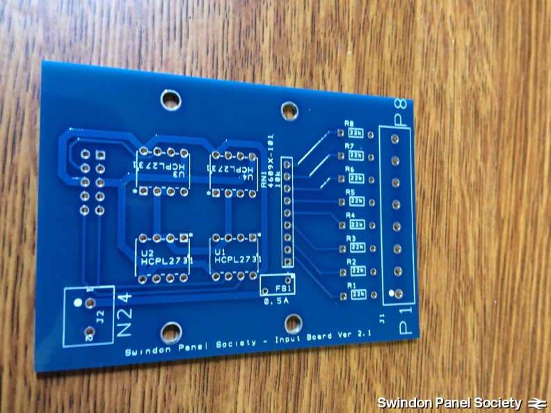
Above: An SPS input board before components are soldered on.
This PCB requires:
– 1 x 2-way screw terminals (for power)
– 1 x 8-way screw terminals (for connecting to the panel)
– 4 x 8-pin IC holders
– 1 x 9-pin resistor array
– 8 x resistors
– 1 x 10-pin DIN header
– 1 x 0.5a fuse